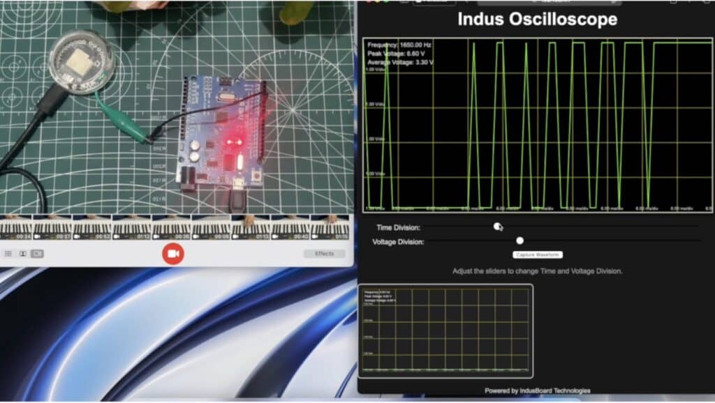
Ossiliscope is an essential test and measurement device that enables us to analyze AC and DC signals, visualize waves, and determine frequency.
However, most traditional oscilloscopes are bulky and large in size, which can be inconvenient when working with microelectronics, designing, and testing small components.
Therefore, we have designed InduScope, a portable oscilloscope that offers IoT connectivity, allowing users to connect it to smart TVs, laptops, and phones. This enables real-time data visualization, display enlargement, and wireless control of the oscilloscope.
In the design process, we utilized the IndusBoard Coin, which incorporates both DAC and ADC functions, enabling us to read signals and use the board as an oscilloscope. Additionally, a circuit was integrated to extend the oscilloscope’s range.

The necessary components are listed below.

Bill of Materials
| Components | Quantity |
| IndusBoard Coin | 1 |
| BNC Connector | 1 |
| Slide switch | 2 |
| Resistors 10K, 100K | 2 |
| IN4148 Diode | 2 |
| Capacitor 1uF | 1 |
IndusScope Circuit
Here, the InduBoard ADC pin is used when connecting many multichannel oscilloscopes.
However, to keep the design simple and easy to manufacture, only one channel oscilloscope is made, and any pins can be used as an ADC. In this case, the four-pin is used as the first channel of the oscilloscope.
After preparing the code, we can directly connect the pin 4 to the probe to see the signal and use it as an oscilloscope. However, to switch between AC/DC signals and extend the range from 0 to 33V DC and 220V AC, we need a special kind of circuit.

Here is the design and circuit needed to achieve this:

The voltage divider circuit consisting of R1 = 100kΩ and R2 = 10kΩ ensures safe input voltage levels for the ESP32-S2 ADC pin by scaling down the input signal. The output voltage is given by:
Vout=Vin×(R2/(R1+R2))
=Vin×(10k/(100k+10k))
≈Vin×0.091
This means the input signal is reduced to about 9.1% of its original amplitude, ensuring it remains within the safe voltage range of the ADC (0–3.3V).
Adding a Capacitor for AC Coupling
To measure AC signals while blocking any DC component, a series capacitor is added. The capacitor should be placed between the BNC input signal line and the voltage divider (R1).
Steps to Add the Capacitor:
- Disconnect the connection between Pin 1 of BNC1 and R1.
- Insert the capacitor in series between these points.
Capacitor Selection:
- Low-frequency signals (50Hz–1kHz): Use a 1µF to 10µF electrolytic capacitor.
- High-frequency signals (10kHz+): Use a 0.1µF to 1µF ceramic capacitor.
If using an electrolytic capacitor, ensure proper polarity—the positive leg connects to the input signal, and the negative leg connects to R1.
Adding Diodes for Overvoltage Protection
To protect the ESP32 ADC pin from voltage spikes, two clamping diodes are added at the output of the voltage divider (R2).
Placement:
- Connect one diode between the ADC pin and 3.3V (anode to ADC pin, cathode to 3.3V).
- Connect the second diode between the ADC pin and GND (cathode to ADC pin, anode to GND).
How It Works:
- Voltages > 3.3V are redirected to 3.3V.
- Voltages < 0V are redirected to GND.
Recommended Diodes:
- Schottky diodes (e.g., 1N5819): Low forward voltage drop.
- Standard diodes (e.g., 1N4148): Alternative option.
Adding a Slide Switch for AC/DC Mode Selection
A slide switch (SW1) allows toggling between AC and DC coupling by bypassing the series capacitor.
How to Connect the Switch:
- Place the switch in parallel with the capacitor.
- Switch closed: Capacitor is bypassed, enabling DC signal measurement.
- Switch open: Capacitor blocks DC components, enabling AC signal measurement.
Why Add These Components?
- Capacitor: Enables AC/DC signal measurement flexibility.
- Diodes: Protect the ESP32 ADC pin from voltage spikes.
- Switch: Allows quick switching between AC and DC coupling modes.
IndusScope Coding

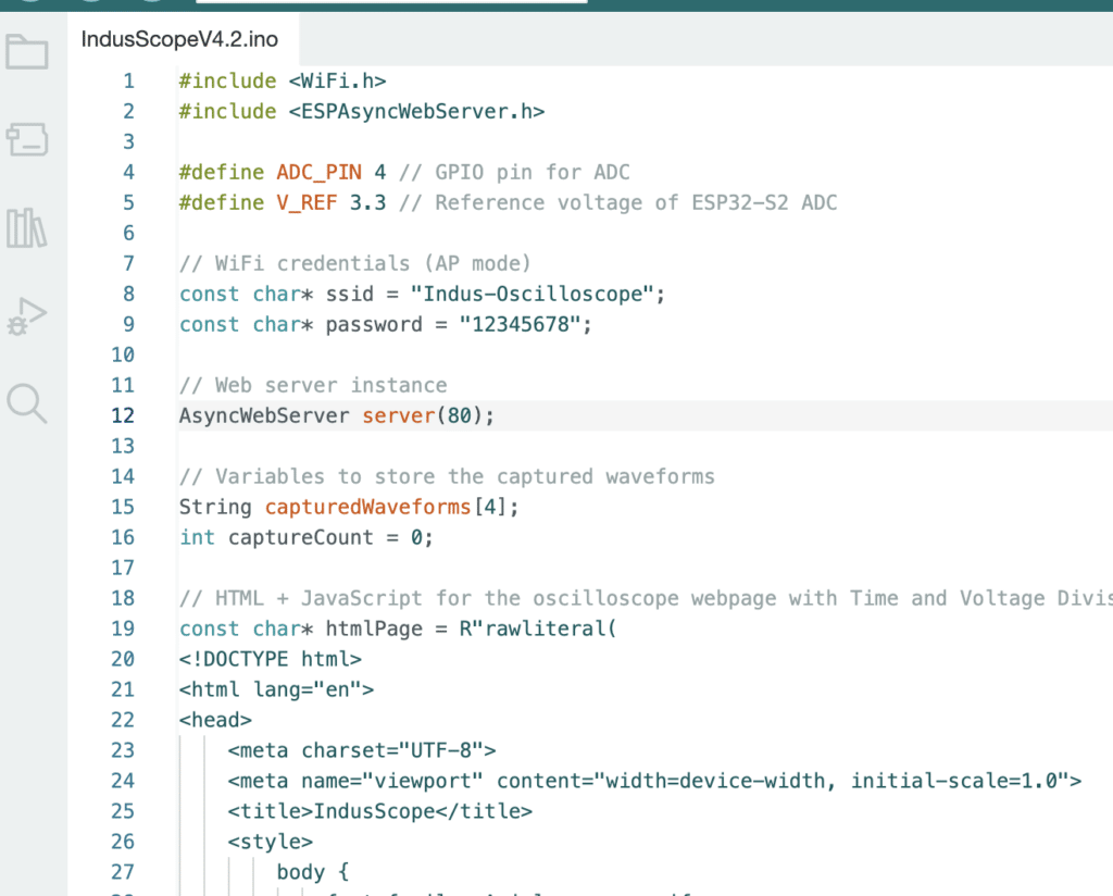
The IndusScope oscilloscope code is designed to sample input signals via the ADC, process the data, and display real-time waveforms on a web interface hosted by the ESP32-S2.
It begins by including essential libraries like WiFi.h for WiFi functionality and ESPAsyncWebServer.h to set up an asynchronous web server.
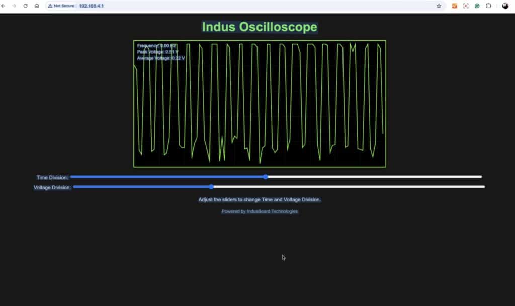
The ADC pin is defined as GPIO4, and the reference voltage for the ADC is set to 3.3V. The ESP32-S2 operates as an Access Point (AP) with the SSID Indus-Oscilloscope and password 12345678, allowing devices to connect directly and access the interface via the IP address http://192.168.4.1.
The web interface is created using HTML, CSS, and JavaScript. It features a canvas for real-time waveform display, sliders to adjust time and voltage scales, and a “Capture Waveform” button to save waveforms as images in a grid.
The drawGrid function renders the oscilloscope grid lines, while the fetchData function periodically retrieves signal data from the ESP32 using an HTTP GET request to the /data endpoint.
The waveform is plotted on the canvas in real time by the updateGraph function.
The signal data is processed in the handleDataRequest function. The ESP32 collects 100 ADC samples at 100µs intervals, calculates the peak voltage (maximum amplitude), average voltage (mean value), and frequency (based on zero-crossings of the waveform).
This data, along with the sampled waveform, is formatted into a JSON response and sent to the web interface. Users can adjust time and voltage divisions using the sliders, and captured waveforms are displayed in the capture grid for further analysis.
This setup transforms the ESP32-S2 into a compact, versatile oscilloscope with a user-friendly web interface.
Testing IndusScope


- Power the oscilloscope and connect to Indus-Oscilloscope using the given credentials.
- Open a browser and navigate to http://192.168.4.1.
- Observe the real-time waveform, adjust settings, and use the capture grid to save waveforms.
